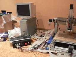
This was the first serious project for my machine. I was tired of all those unorganized cables and decided to put al the controls into one nice box. I could not find any suitable aluminum enclosure: some were too small, some were too ugly, some had such a configuration that made machining very difficult or impossible. Finally, I decided to go with a steel enclosure. It had very convenient front and rear panels and a plenty of free space.
I must admit that at first I was a bit scared because cutting steel was not what I intended my machine to do. However, since no other alternatives were available, I decided to try and see what happens.
Click on the images to enlarge.
|
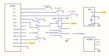
The very first thing I had to do was to draw a schematic for my controller box wiring. I had all the limit switches installed, and connecting them was straightforward. I wanted to implement the Spindle Start relay so that Mach3 will automatically start and stop my spindle. This required some additional work on the E-Stop switch wiring: I had to add the third section to the switch to be able to shut the relay off in case of emergency. You may notice that there are two grounds in the circuit. The signal ground is designated with the flat bar and has a star connection point at the PSU "V-" terminal (0V potential). Another one is the safety ground and is connected to all metal parts of the enclosure. I decided to make a PSU my main grounding point in the star grounding system. It has a very clever design and both signal and safety grounds are present there. Also, there is an internal connection between these grounds inside the PSU, and it is recommended to connect grounds in only one point of the circuit. Please note that there is no additional PSU for relay. I decided to use 48V relay because I really do not think that additional PSU is an elegant solution. |
 |
|
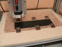
Now I had to find a way to fix the panels for machining. Since the panels were not flat but had a U-shape I've made a couple of cuts in the table. This allowed me to set up the panels very quickly because they ended up in the exact same place. |
|
|
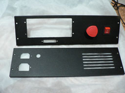
I have made some cutouts and you can see the finished panels on the picture to the right. On the "CNC pics and videos" page you will find a video of my machine cutting these particular panels. I have decided to experiment with a feed rate and depth of cut. The cutouts were cut with approximately 9 ipm feed rate and 0.01" depth of cut. This combination worked, but it took too much time. The grill was cut at 2.2 ipm feed rate and 0.05" depth of cut. Since my panels were 0.05" thick it took one pass to cut the grill. I had no problems slotting at 0.05" depth of cut with 3-fluted carbide endmills. I was using cutting oil while cutting for better results. |
|
|
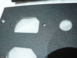
Here is the close-up of the cutouts. I must say that I am impressed with the tolerances of my machine. I have measured the cutouts ad they are +/- 0.002". This is very good for a DIY homemade CNC machine! |
|
|
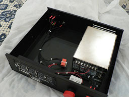
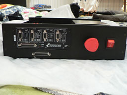
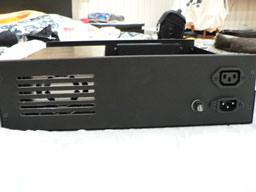
Here are the pictures of the assembled unit. For those interested in the drawings here are the DXF documents of the front and back panels. Note however, that cutout dimensions for switches, outlets and fuses may vary depending on the particular parts you're using. |
|