Limit switches are an important part of any CNC machine. Very important. If you do not want to crash your axes accidentally, of course. Mounting options for limit switches vary widely and heavily depend on the machine design. I am going to tell you how I installed and wired limit switches on my machine.
If you read about my CNC controller enclosure project, you may remember that the circuit there included limit switches. However, installation and wiring of these switches was not covered in that article. I will try to fill that gap.
The very first (and obvious) question was: "what switches should I use?" I have made an extensive research regarding the models available and their pricing. The results were quite sad: precise end switches are very expensive here. I needed six limit switches and this may have cost me 100$ or more. I was not prepared to pay this much, and I did not need the precision these switches offer. So I decided to buy some general lever-activated miniature switches and hope that they will be accurate enough for my tasks. This assumption turned out correct, more on this later however.
Click on the pictures to enlarge.
|
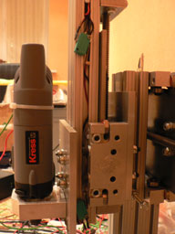
I started with the Z-axis since the mounting was very straightforward. The green switches on the picture are the miniature lever-activated switches with a small roller at the end of the lever. I positioned them so that the bearings trip the switches at the extremes of the axis. 80/20 extrusion is very convenient for mounting switches. The holes in the limit switches accepts M3 (or #4) screws. And I had to use additional washers that fitted the wider extrusion slot. As you can see, I have used an extrusion slot as a protection conduit for switches wires. |
 |
|
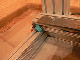
The mounting style of the Y-axis switches is very much the same as the Z-axis ones. Again, the switches are positioned so that the linear carriage bearings trip the switches at the extremes of the Y-axis. |
|
|
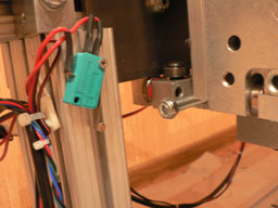
The most difficult part was the X-axis switches. There seemed to be no way they could be mounted to be tripped by the linear carriage bearings because the rail is too wide and thus the carriages are too far away from the extrusion. However, after some thinking, I could find a way around it. I had some long carriage bolts left from the build and I had an idea of using them as the actuators for the switch. I put the bolts into the Z-axis extrusion. The length was perfect, but the bold had too much offset and could not trip the switch. The solution was to screw a nut, which extended the diameter of the bolt end. That was enough to trip the switch. |
|
Please note that all the soldered ends are protected with a heat shrink tubing to avoid chips getting in and accidentally shorting the contacts.
As for precision, I did some testing homing the machine to the limits and measuring an absolute position difference. These cheap switches gave me approximately 0.008" positioning precision (0.2 mm). They are not very repeatable: sometimes I got a 0.002" precision (0.05 mm) but more often something in between. Now, I do not need a dead-set home position, since most of the time I reference from the edge of the part. And I do not have the fixtures on my table yet. So for now this precision is quite reasonable and, anyway, the main purpose of these switches is to protect the axes from overtravel. Which they do perfectly. And I see an acceptably precise homing as a pleasant bonus to their main function.